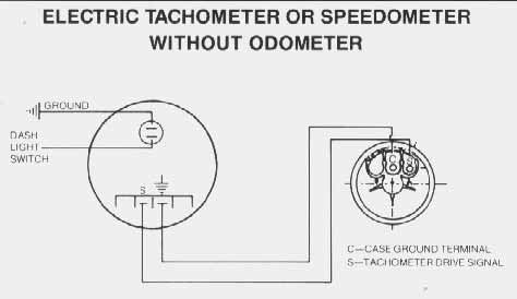
Slip the mounting bracket or the vdo spin lok clamp over the back of the ta chometer as shown in diagram b. Connect the 12 volt wire from the sw 4.
 Vdo Marine 3 3 8 85mm Viewline Tach W Multifunction Display 0
Click here for auto meter classic instruments defi or isspro instructions.

Vdo marine diesel tachometer wiring diagram. These instructions are for vdo gauges and accessories only. See page 4 for mounting options and instructions wiring the gauge illustration a. Put the instrument into the drill hole from the back.
This sensor is avail able from your auto parts dealer. The size of the tachometer youre installing. Mount the gauge and secure with the vdo spin lok clamp.
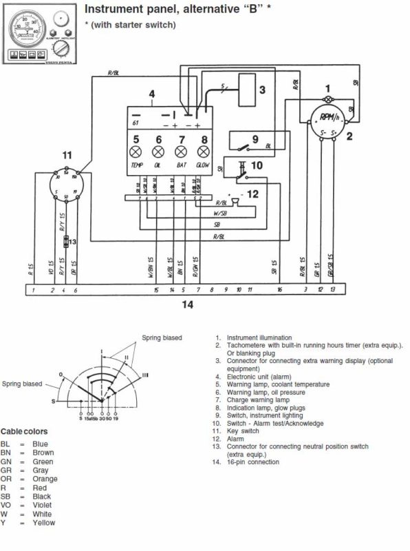
This signal comes from the windings in the alternator before its rectified to dc and regulated to the system charge voltage. Adjust the instrument so that the gauge is level and fasten it to the stud bolts on the rear side of the panel using the flush mount fixing bracket a2c59510864. The highest precision and the use of pioneering technologies are as important to us as the ease of use and appealing design.
The sensor necessary to provide the signal to your new vdo tachometer is not included. A the battery constant power after the fuse box or user supplied in line fuse 5 amp fast blow. At this point the installation and wiring of your tachometer is complete.
Part numbers forhe t vdo generator sensor is part 340 001vdos inductive sensor is part 340 020 1. Place the flush mount seal a2c53215641 on the instrument glass. If the gauge is too snug use a file to slightly enlarge the opening.
Since diesel engines do not have an ignition system the engine speed signal is supplied from the alternator ac tap or sometimes called the r terminal. Tighten until the tachometer can no longer be ro tated by hand. Vdo marine supplies solutions for pleasure boats yachts and sailing boats since 1958 wherewith with 60 years of experience vdo marine stands as one of the oldest reliable marine electronics suppliers in the industry.
Connect the wire from the light switch to the remaining terminal on the lamp socket. Connect the wire from the ignition coil as shown in diagram d to the 2 terminal on t 6. Route wires from the instrument to.
Refer to diagram b for dimensions. View and download vdo tachometer installation instructions manual online. Please note that if you have a problem opening the pdf files just by clicking on the link please right click your mouse button over the file name and select save target as to your desktop.
Tachometer measuring instruments pdf manual download.
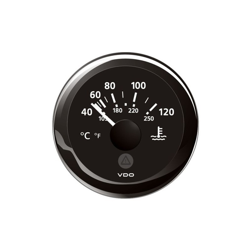 Vdo Viewline Coolant Temperature 120 C Black 52mm
Db8894 Vdo Tachometer Wiring Diagram Diesel Wiring Resources
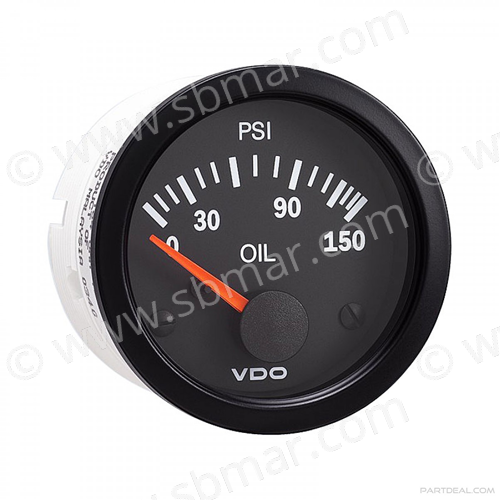 Vdo Engine Oil Pressure Gauge 0 150 Psi Seaboard Marine
 Vdo Xtreme Tachometer Wiring Diagram Wiring Diagram
 Vdo Performance Instruments
 Viewline Onyx Fuel Gauge 12 24v Use With 3 180 Ohm Sender Vdo
 7df Vdo Diesel Tachometer Wiring Wiring Resources
Https Www Vdo Instruments Com Media Instructions 0 20515 20010 20444 20 20tachometer 20installation 20and 20operations 20instructions 20ducati Rotax Pdf
 Pin On Tachometer
 Vdo Tachometer Wiring Color Wiring Diagrams Blog
 Manuals For Vdo Equipment Marine Diesel Basics


 Vdo Xtreme Tachometer Wiring Diagram Wiring Diagram
 Vdo 2c53218716 5 Ocean Yachts Oem Black Marine Boat Tachometer
 Vdo Fuel Gauge Wiring Wiring Diagrams
 D2 55 Wiring Diagram Dash Ac Dc Marine Inc
 How To Install A Tachometer Signal Wire On Your Diesel Alternator
 Vdo Xtreme Tachometer Wiring Diagram Wiring Diagram
No comments:
Post a Comment