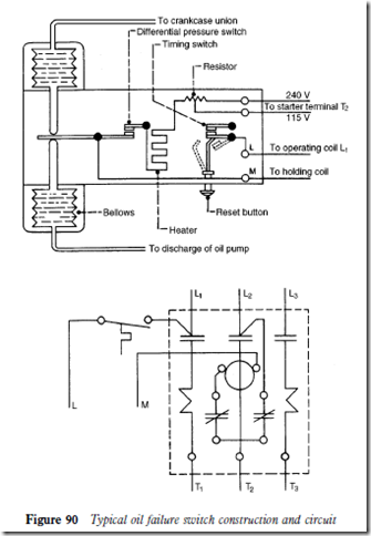
Oil pressure cutout for pressure lubricated refrigeration compressors. If the lube oil pressure does not build up to the scale.
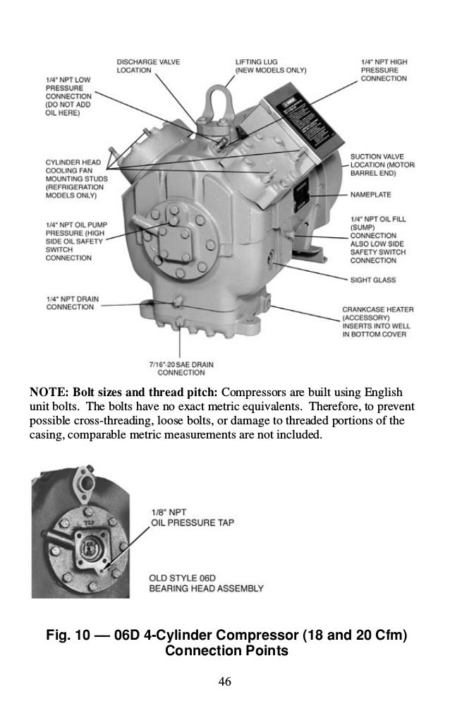
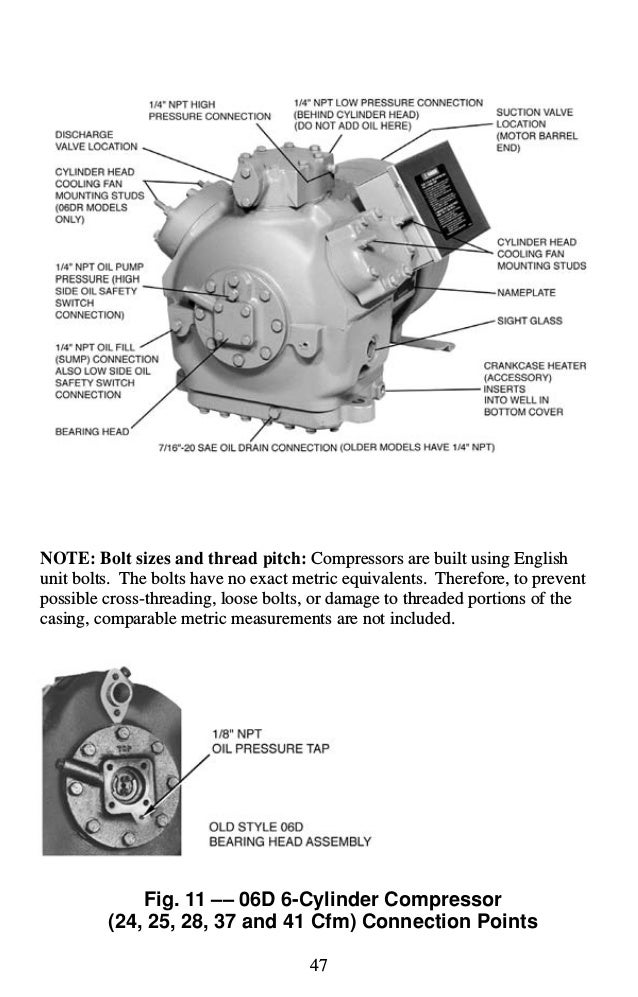 Service Guide Carlyle Compressor
Pre wired distribution power block.
Refrigeration oil pressure switch wiring diagram. The electrical circuit is divided into two completely separate circuits a safety circuit and an operational circuit. Low refrigeration pressure switches the low pressure switch is typically an automatic reset switch that will reset itself when the pressure on the low pressure side of the refrigeration systems returns to normal or above the setting on the switch. Net oil pressure is the difference between the oil gage pressure and the refrigerant pressure in.
Upon an initial start of the compressor or if the oil pressure drops during the running cycle the time delay heater is energized. Factory wired control panel has. How to do wiring and testing of danfoss oil pressure switch in airconditioning and refrigeration system.
These refrigerator systems conform to the commercial refrigeration manufacturers association health and sanitation standard crs s1 86. Are cycled on and off via low pressure settings by a central controller to match refrigeration capacity with load requirements. If the oil pump is generating 115 psi and the suction pressure is 70 psi the oil pressure is 45 psi.
Installation service manual parallel compressors enviroguard save these instructions for future reference. The factory set pressure adjustment provides operation to the compressor manufacturers specification. If the oil pressure falls below the minimum for a predetermined time the control contacts open stopping the refrigeration compressor.
The p45 control measures the net oil pressure available to circulate oil through the lubrication system. Most compressors need a minimum 10psi to lubricate all moving parts. Now if this switchpc is closed and the control is energized power to v1 or v2 then the heater h is energized.
Oil pressure as measured with a gauge is the sum of the crankcase pressure suction and pressure arising at the pump. Rejection switch should be set to work in the useful pressure not on the total pressure. The control scale setting should be 9 psi 62 kpa.
If there is no oil pressure on starting or if the oil pressure falls below the set pressure during operation the compressor will stop after the release time has elapsed. Lube oil pressure required to the bearings is 9 psi 62 kpa oil pump pressure minus crankcase pressure. So when we start the compressor power is applied to v1 or to v and once oil pressure builds up to the 9 12 psig range it will open switch pc and de energize the heater.
 Seal Oil System An Overview Sciencedirect Topics
 China Ops2 Oil Pressure Differential Switch Copeland Compressor
 Danfoss Cs Compressor Switches
 Wiring Diagram For 220 Volt Submersible Pump Well Pump Pressure

 Danfoss Oil Pressure Switch Wiring And Testing Youtube
 Oil Separators Unicla

 Wiring Diagram For 220 Volt Air Compressor Air Compressor
Https Climate Emerson Com Documents Dwm Copeland Semi Hermetic Compressors Oil Pressure Differential Switch Ops2 Technical Information En Gb 4229040 Pdf
 Refrigeration Pressure Switches Hvac Air Conditioner And Heat
Https Docs Johnsoncontrols Com Bas Api Khub Documents 1lkwnhhpigt09s8pifabjw Content

 Oil Pressure Controls Hvac School
 Differential Pressure Switch Mp55 Differential Pressure
 Johnson Controls High Pressure Controls Youtube
 Plc Wiring Vfd Wiring Skills Hands On Electrical Training
Service Guide Carlyle Compressor
No comments:
Post a Comment