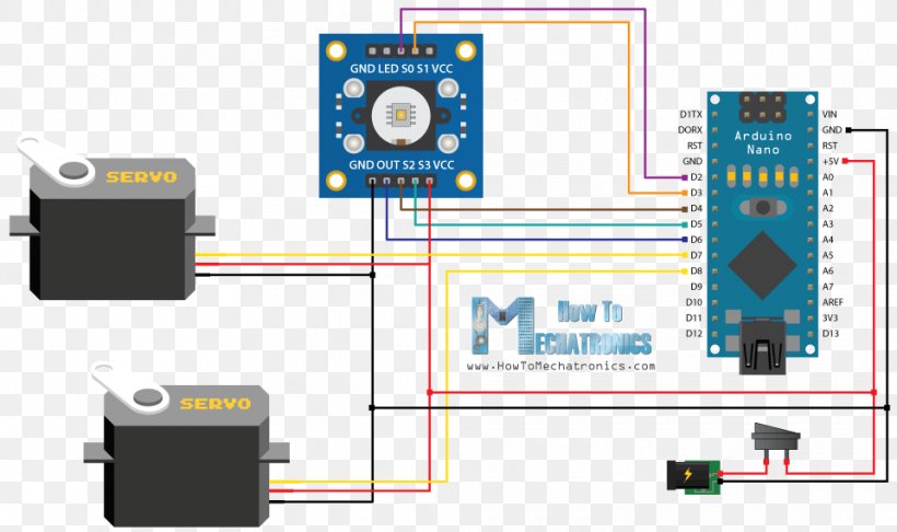
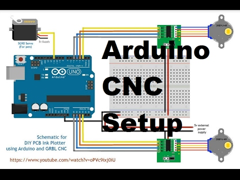
Microcontrollers are an excellent way of controlling and. The above wiring diagram shows the pin out on a arduino uno micro controller board needed to let the sample source code control the robotic arm and communicate with a windows pc running mecon motion control software.
 How Servo Motor Works Interface It With Arduino Last Minute
The gears in the motors are easily subjected to wear and tear.

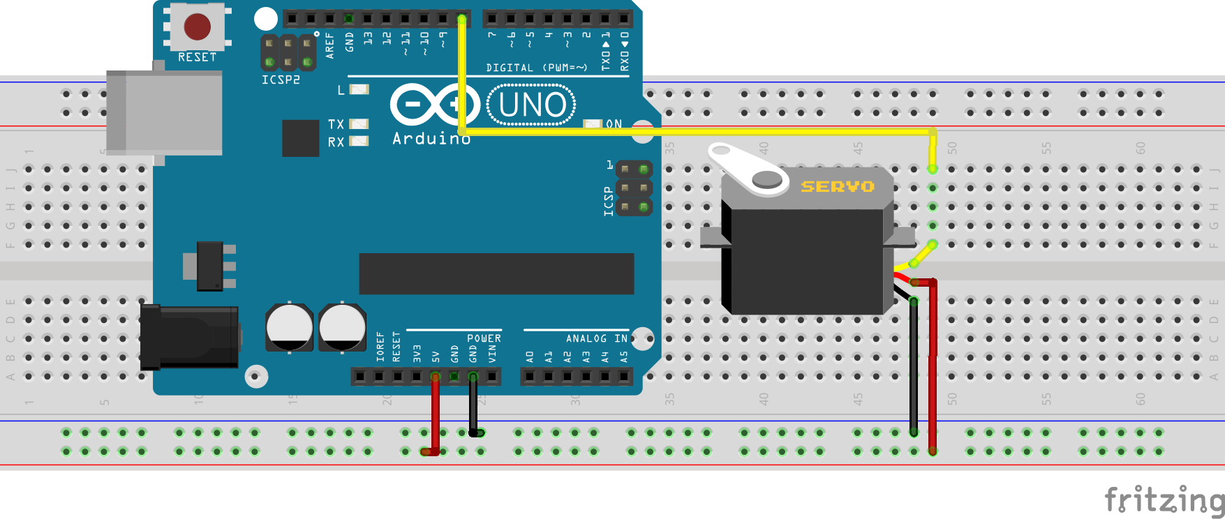
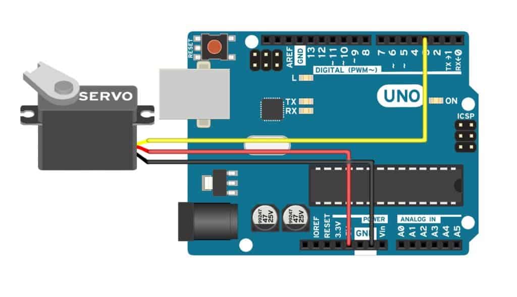
Arduino servo motor wiring diagram. This project is an easy way to understand the basics of servo movement with an arduino uno. The power wire is typically red and should be connected to the 5v pin on the arduino or genuino board. Almost all hobby servo motors can rotate only from 00 to 1800 due to their gear arrangement so make sure you project can live with the half circle if no you can prefer for a 00 to 3600 motor or modify the motor to make a full circle.
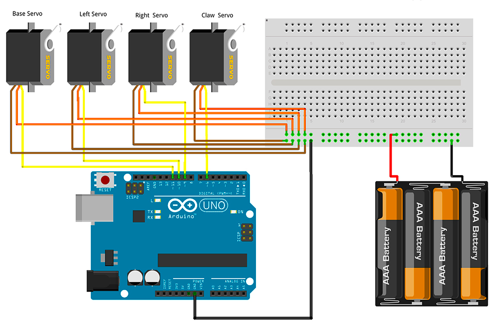
Connect to the motor to the arduino as shown in the table below. Servo yellow wire pwm9 pin arduino. With this simple arduino project you can servo motor using a remote control.
Armuno armio mearm basic arduino servo wire connections using a breadboard and jumper wires. Vcc pin typically red needs to be connected to vcc 5v gnd pin typically black or brown needs to be connected to gnd 0v. Servo motor is a component that can rotate its handle usually between 00 and 1800.
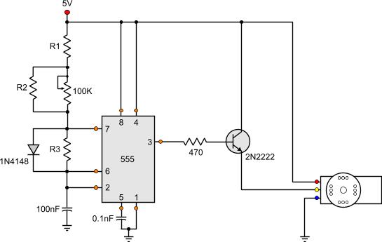
Most servo motors run on 5v so you can attach the red lead to the arduinos 5v pin. The best thing about a servo motor is that it can be connected directly to an arduino. A better look at the circuit board dc motor and potentiometer.
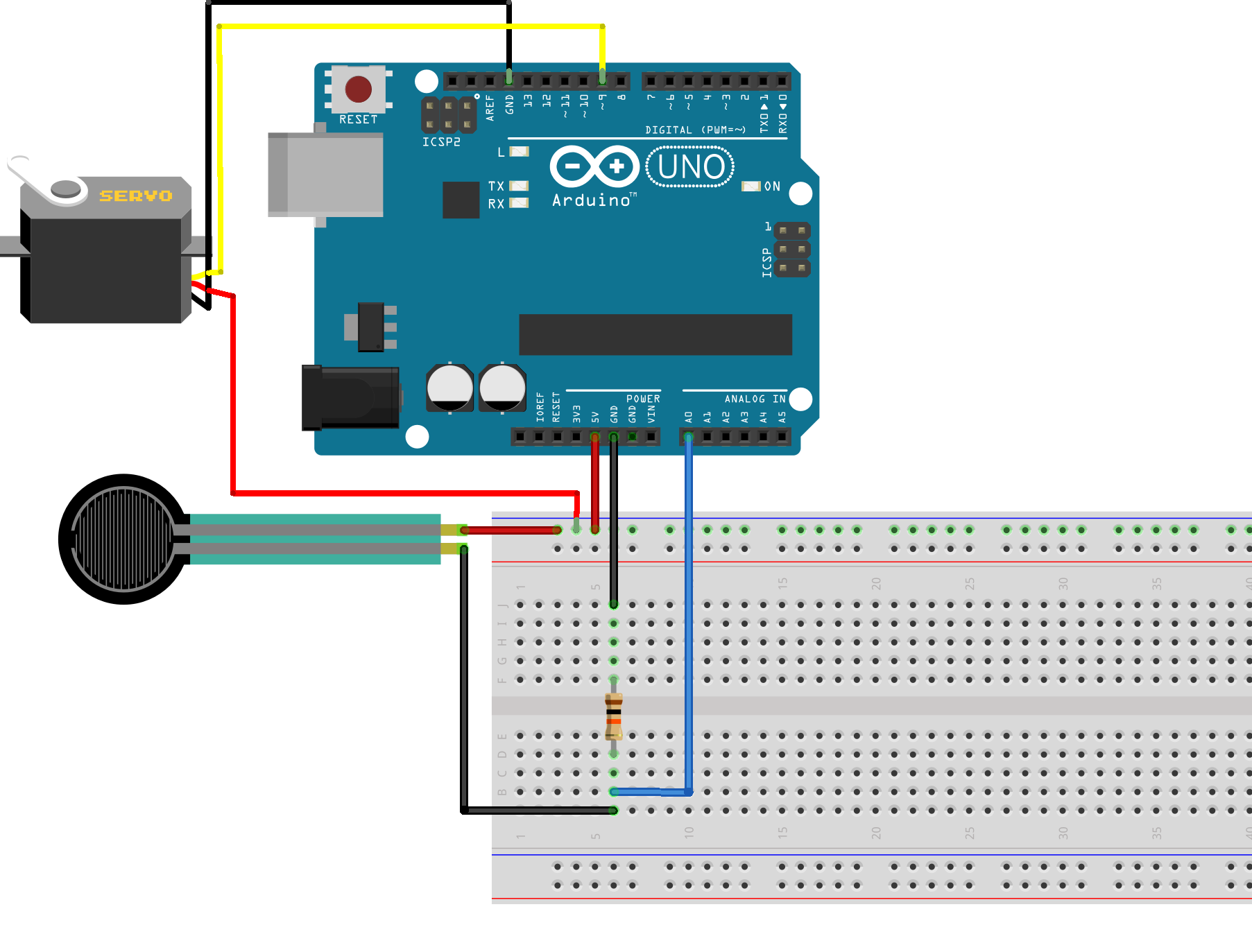
Click on this link and go to wire section for wiring diagrams. The blue wire is connected from the signal pin of the servo motor to pin 3 of the arduino. Find out more below.
Power ground and signal. It used to control the angular position of the object. Servo motors that dont produce high torque typically contain plastic gears.
The power wire is typically red and should be connected to the 5v pin on the arduino or genuino board. The ground wire is typically black or brown and should be connected to a ground pin on the board. To begin wire this circuit.
Servo brown wire ground pin arduino. Power ground and signal. Servo red wire 5v pin arduino.
The red wire is connected from the signal pin of the servo motor to the 5v pin of the arduino. Arduino to servo motor wiring diagram. Servo motors have three wires.
The ground wire is typically black or brown and should be connected to a ground pin on the board. Watch this tektips video to learn the easy process of wiring an arduino to a clearpath integrated servo motor. Servo motors have three wires.
The black wire is connected from the ground pin of the servo motor to the gnd pin of the arduino. The servo motor used in this example includes three pins.
 Wiring Diagram Arduino Servomotor Color Vehicle Audio Png
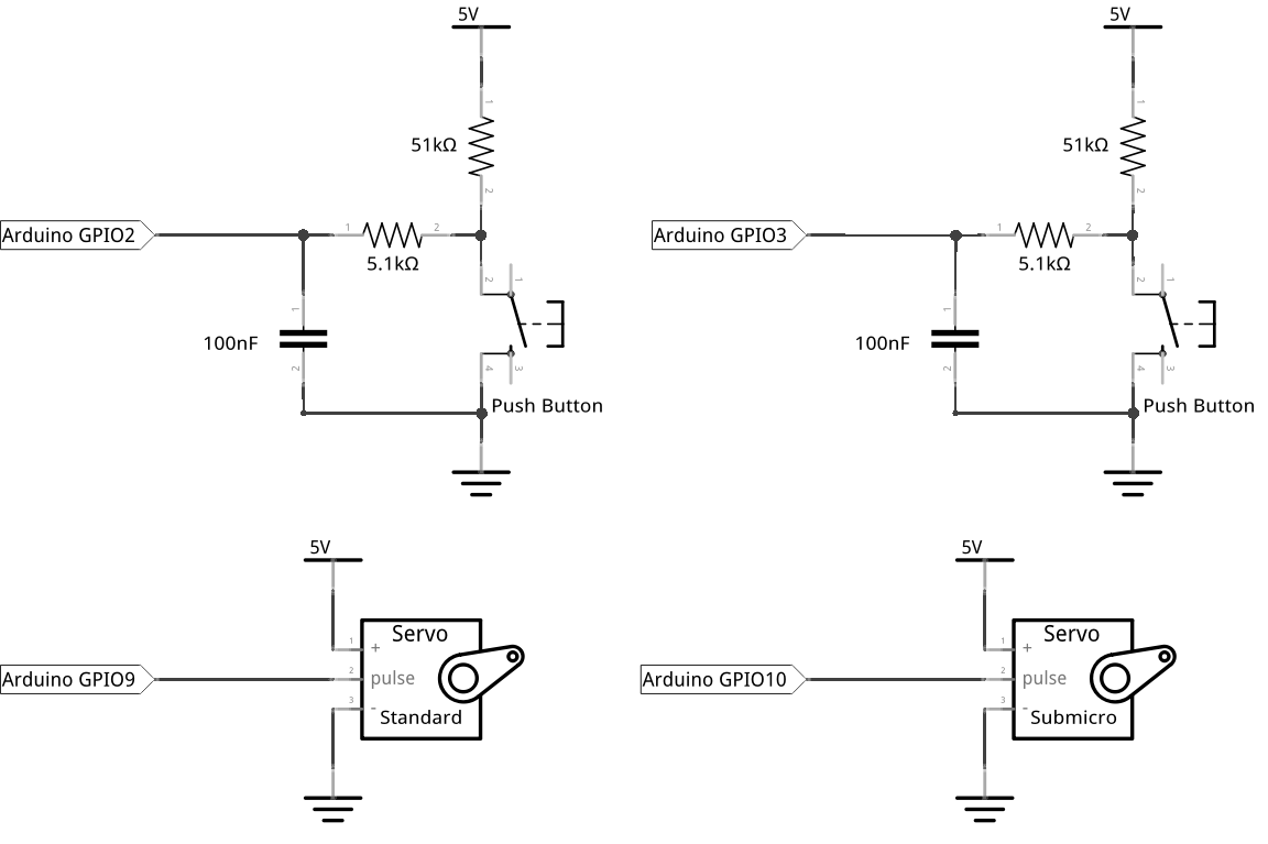
 Control Servo With Light 3 Steps Instructables
 Armuno Mearm Arduino Servo Wire Schematic
 Using The Sg90 Servo Motor With An Arduino Electronics Lab
 Servo Sg90 Arduino Wiring Diagram Arduino Servo Motor Arduino
 Control A Servo With A Force Resistive Sensor On Arduino Arduino
 Servo Motor Control And Interfacing Wiht Arduino
 How To Interface Arduino With Servo Motor Easytronic
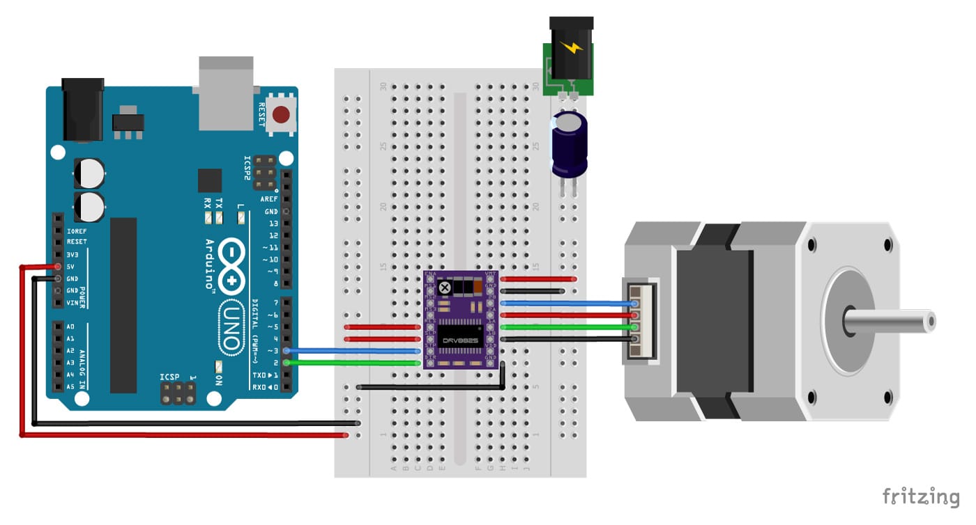 Stepper Motor With Drv8825 And Arduino Tutorial 4 Examples
Circuit For Ultrasonic Sensor Based Distance Measurement The Logic
 Interfacing Of Arduino With Servo Motor The Definitive Guide
 Dl 4797 Servo Motor Wiring Diagram Servo Motor Wiring Diagram Hecho
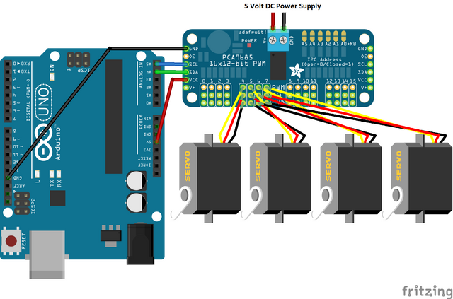 Adafruit Pca9685 Pwm Servo Driver Setup Arduino Library Use Shown
 Controlling Servos Onion Omega2 Arduino Dock Starter Kit

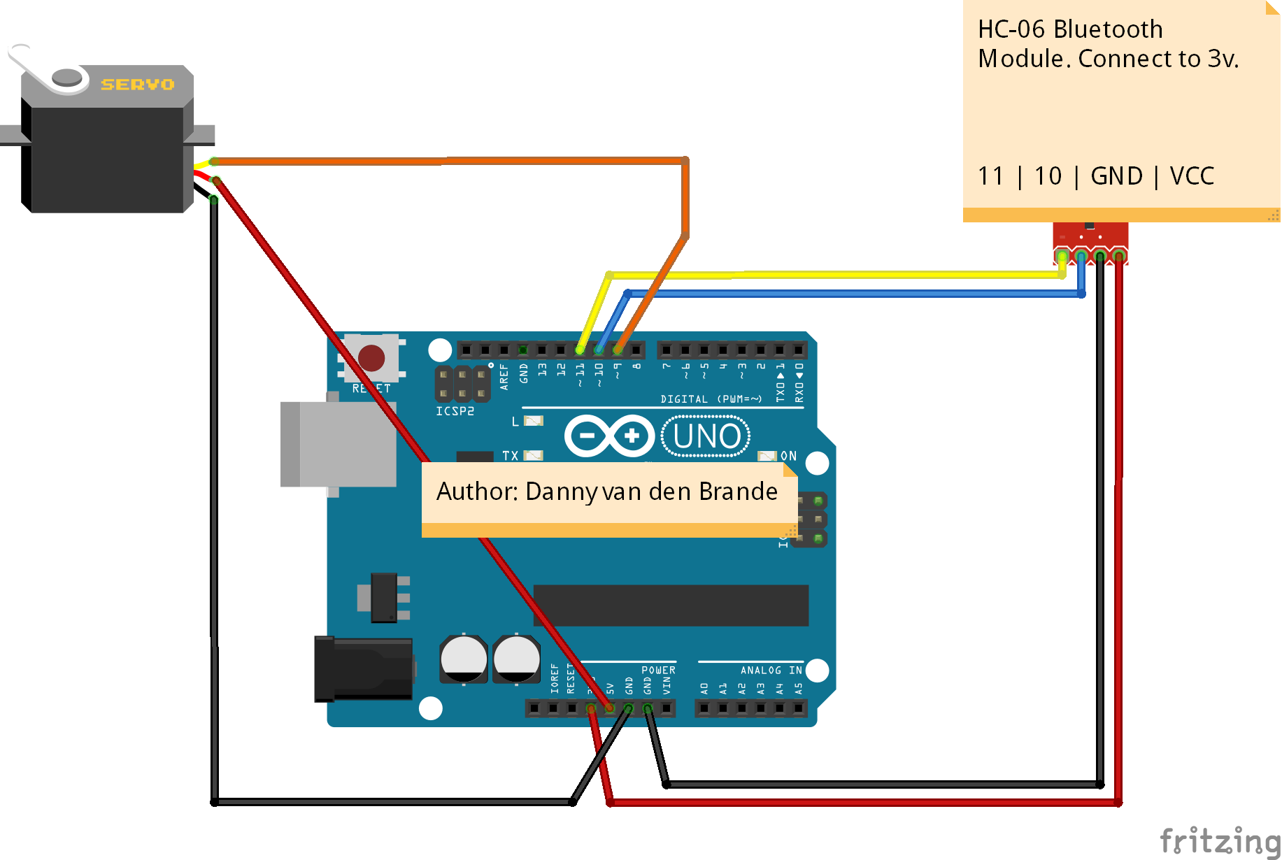 Arduino Android Bluetooth Servo Motor Control Android App

No comments:
Post a Comment