A wiring diagram normally offers info regarding the family member setting. Another factor is if the compressor is single phase or three phase power.
 Capacitors For Compressor Wiring Diagram Schema Wiring Diagrams
A wiring diagram is a streamlined traditional photographic depiction of an electrical circuit.
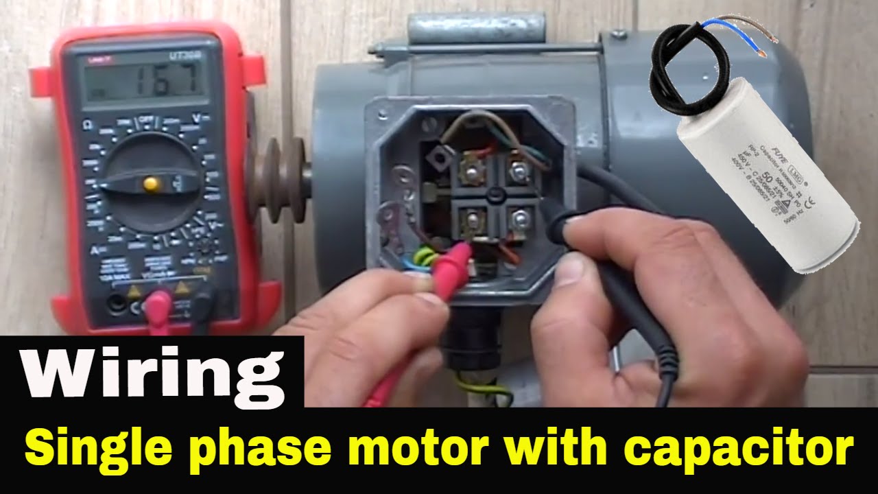
Single phase ac compressor wiring diagram. Single phase motors are used to power everything from fans to shop tools to air conditioners. As you know that we use in every place ac motor for different types of work. A home air conditioner is generally a single phase unit which is what this article concentrates on.
It shows the elements of the circuit as streamlined shapes as well as the power and signal links in between the tools. This dictates the configuration of the wiring. Residential power is usually in the form of 110 to 120 volts or 220 to 240 volts.
Some motors allow both 120 volt and 240 volt wiring by providing a combination of wires for doing so. These tips can be used on most electric motor brands such as weg baldor. David talks about basic compressor wiring.
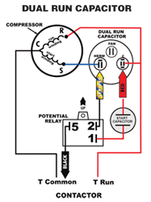
Compressor wiring diagram single phase. Collection of baldor single phase motor wiring diagram. Capacitor start capacitor run induction motors are single phase induction motors that have a capacitor in the start winding and in the run winding as shown in figure 12 and 13 wiring diagram.
This type of motor is designed to provide strong starting torque and strong running for applications such as large water pumps. Single phase compressor for air condition. The complete guide of single phase motor wiring with circuit breaker and contactor diagram.
A main concern is the amperage requirements of the compressor. This dictates the size of the wires. In this video jamie shows you how to read a wiring diagram and the basics of hooking up an electric air compressor motor.
There are main two types of ac motors which are single phase and 3 phase. Compressor wiring diagram single phase wiring diagram is a simplified standard pictorial representation of an electrical circuit. Wiring a motor for 230 volts is the same as wiring for 220 or 240 volts.
In air condition systemcompressor is a main component to pump the refrigerant circulation in systemit like our heart to pump a blood all around human systemif this part breakdown or have a problemall system is paralyze. It shows the components of the circuit as simplified shapes and the talent and signal contacts in the midst of the devices. Submersible pump control box wiring diagram for 3 wire single phase 3 wire submersible pump control box wiring diagram or single phase submersible pump starter wiring diagram and wiring installation guide single phase pressor for air condition electrical air conditioner soft starter series including 1 single phase air conditioner soft starter tl.
 Nordyne Compressor Wiring Diagram Wiring Diagram E11
 Af771f Single Phase Compressor Wiring Diagrams Wiring Resources

 Baldor Single Phase 230v Motor Wiring Diagram Wiring Diagrams Blog

 Sc 3004 Motor Wiring Diagram In Addition 3 Phase Air Pressor
 Nice Single Phase Wiring Diagram For House 230 Vac Single Phase
 Types Of Single Phase Induction Motor How To Start Running
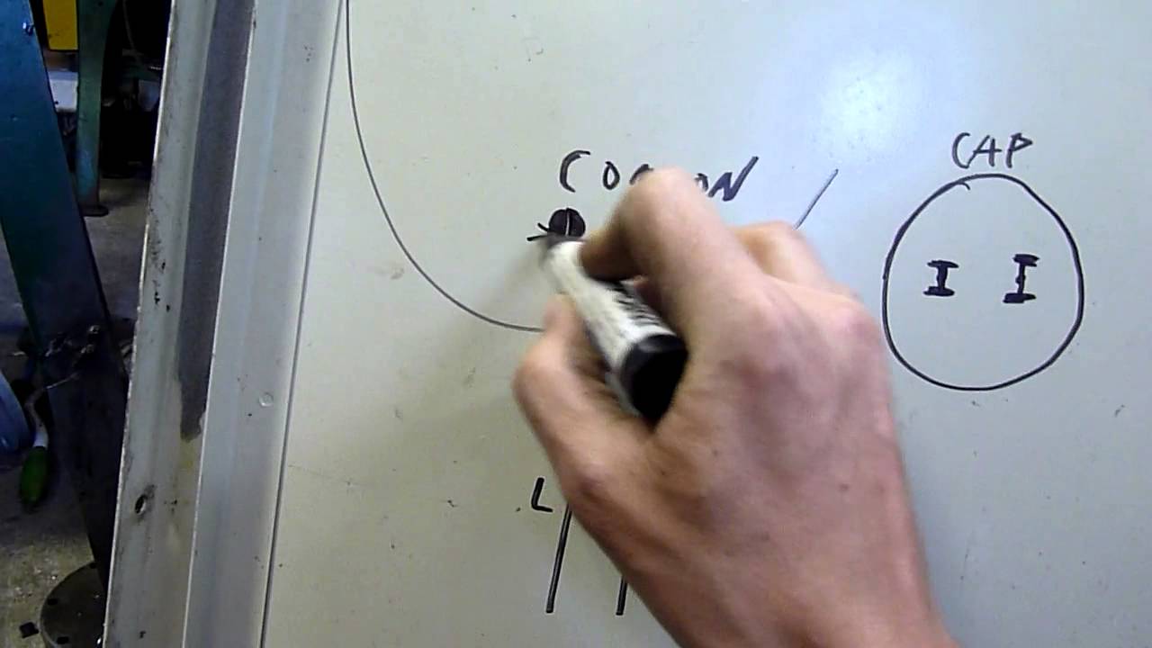 Aircon Compressor Wiring Crash Course Youtube
 How To Wire Single Phase Motor With Start Run Permanent Capacitors
 Diagnosing Issues In A 3 Phase Air Conditioning Compressor Hvac
 Century 5hp Electric Motor Wiring Diagram Wiring Diagram E7
 Electrical Wiring Diagrams For Air Conditioning Systems Part Two
 Single Phase Motor Wiring Diagram With Capacitor Start Di 2020
 Wiring Diagram Easy Set Up Air Conditioning Wiring Diagrams Blog
 Wiring Diagram For 220 Volt Single Phase Motor Ac Capacitor
 Amazon Com Intermatic Cd1 024r Compressor Defender Protects
230 Volt Single Phase Motor Wiring Diagram
No comments:
Post a Comment