This solar usb battery charger circuit can be used to charge any device which can be charge from computer usb port. Diy solar cell phone or usb charger circuit diagram.

5 volts of dc voltage and 100ma of current is being provided by the usb outlet which is well enough for the mobile phone charging slowly.

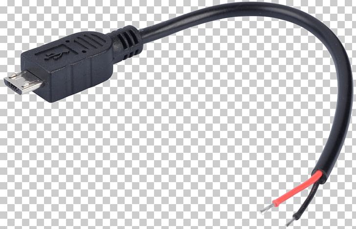
Usb charger cell phone charger wiring diagram. Now simply use any power cable and connect it to the usb pin of the module and the other end to your mobile phone. For the charging of your mobile phone this circuit provides you a regulated voltage of 47 volts. Typically it uses black black red and white wire colours.
As shown in the above wiring diagram simply solder the solar panel in parallel and connect them to a boost converter module through a switch. In order to make your pc charge your phone through a usb cable wo installing any special drivers or software. The cable may be utilized to transfer information from 1 apparatus to another.
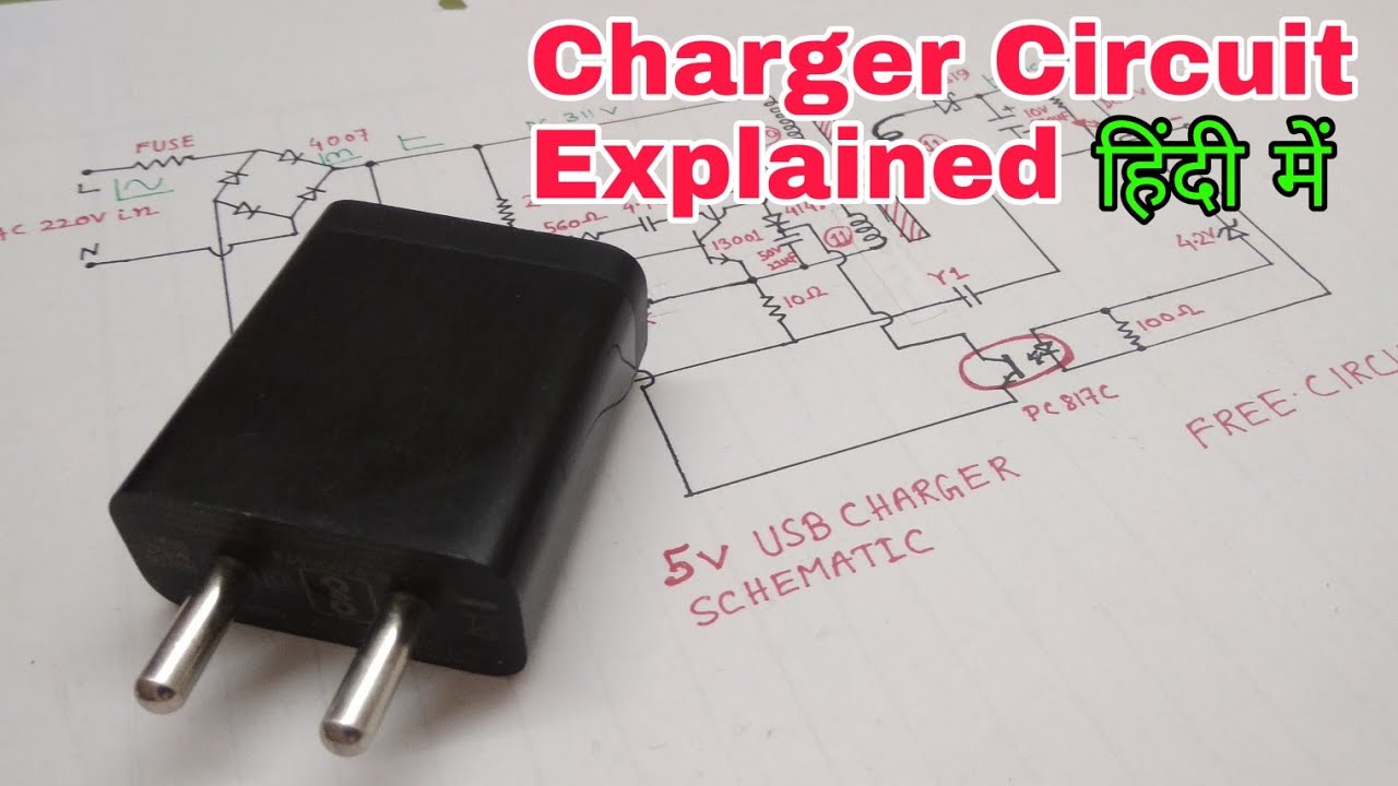
Here is the schematic of a simple diy solar cell phone or usb charger circuit. This dc supply can be used to charge mobiles as well as the power source for digital circuits breadboard circuits ics microcontrollers etc. In accordance with lg phone usb charger wiring diagram there are just four wires used in the cable.
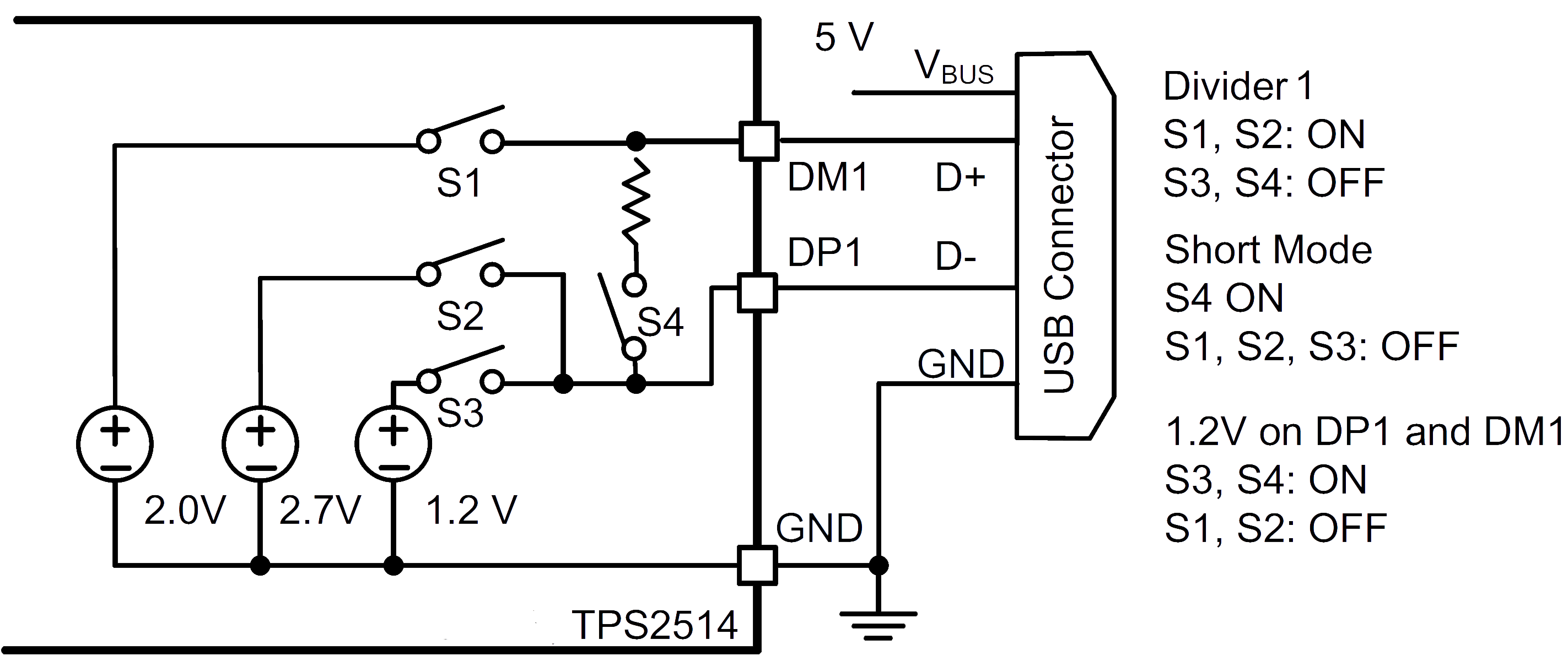
Shorting pin 4 to pin 2 and to pin 5 via r200kohm causes the phone to go into charge mode. Here is the simple solar battery charger circuit designed to charge a 5 14v battery using lm317 voltage regulator. Circuit diagram of cell phone solar charger is given below.
The phone supplies 214vdc to pin x before anything is plugged into it. Black wire serves as ground exactly like in every other apparatus. Mobile phones generally charge with 5v regulated dc supply so basically we are going to build a circuit diagram for 5v regulated dc supply from 220 ac.
As usb outlets can give 5v dc and 100ma of current. Short pins 2 and 3 then put a 200k ohm resistor between pins 4 and 5. It is sufficient for slow charging of mobile phones so they can be used to charge the mobile phones.
Now the charging of your mobiles has been made easy with the help of usb outlets present in the laptop and pc. Cell phone charger wiring diagram wiring diagram is a simplified customary pictorial representation of an electrical circuitit shows the components of the circuit as simplified shapes and the capacity and signal links together with the devices. Battery charger circuit solar panel battery solar charger electrical projects electrical wiring electronics projects arduino solar panel system solar panels.
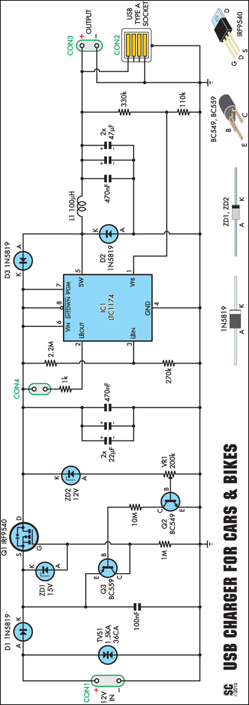
The mobile charger circuit presented in this project can give 47v of synchronized voltage wysiwygimageuploadfor charging the phone. The red one is to get sure cable with dc power of 5 liter. Non usb 12 volt phone charger wiring diagram there are several sorts of electronics available on the market.
For example mp3 players cell phone iphone etc. The majority of them use usb cable.
 Battery Charger Ac Adapter Wiring Diagram Electric Power Png
 Circuit Diagram Usb Charger Wiring Diagram
Mobile Charger Circuit Diagram Pdf
 Cell Phone Charger Cord Wiring Diagram Wiring Diagrams All
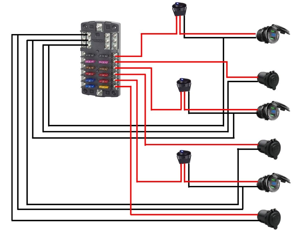 Installing Usb Chargers And 12v Sockets Weekender Van Life
 How To Build A Solar Powered Usb Charger For Your Phone
 Circuit Diagram And Electronic Circuits Projects Chargers
 Usb Charger Circuit Diagram How Mobile Charger Works Free
 Battery Charger Usb Flashlight Wiring Diagram Phone Transparent
 Usb Mobile Charger Circuit Diagram
 Diy Usb Condom Circuit

 Battery Charger Wikipedia
 Diy Solar Cell Phone Or Usb Charger Circuit Diagram Solar
 Usb Charger Schematic Wiring Library
 Schematics Com Pwm Controlled Dc To Dc Cell Phone Charger
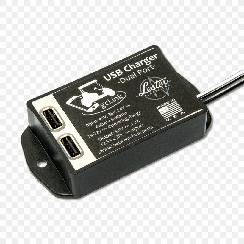
 Battery Charger Electrical Cable Electrical Connector Micro Usb
No comments:
Post a Comment